I/O Circuit Connection diagram
* Download CAD file or product manual for larger image/text and more detail.
Output circuit
PNP
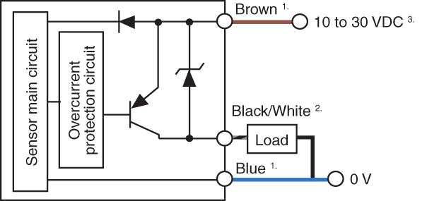
1. GV-22 and GV-22P do not have brown/blue wires. The internal structure of
the power supply line is the same as GV-21.
2. Black: Control output 1/White: Control output 2
3. If expansion units are added, supply voltage must be 11 to 30 VDC.
Input circuit
Emission stop input, Bank switching input, Shift input, Timing input
PNP
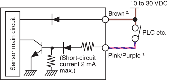
1. Pink: Bank switching input/Shift input/Timing input,
Purple: Emission stop input
2. GV-22 and GV-22P do not have brown/blue wires. The internal structure of
the power supply line is the same as GV-21.