Observation and Measurement of Piping Joints and Valves Using a Digital Microscope
Factories are built with various pipes used to carry a wide variety of liquids and gases. Joints and valves are used to connect these pipes and to control the fluids within. This section introduces observation and measurement examples of piping joints and valves using a digital microscope.
- Piping joint and valve–related terms
- Types of joints
- Types of valves
- Piping connection methods
- Typical piping materials
- Observation and measurement examples of piping, joints, and valves using a digital microscope
Piping joint and valve–related terms
- Fluid
- The liquid or gas that flows through piping.
- Joints
- Components that connect pipes to other pipes, valves, and other parts. Joints can be used to change the direction of piping, branch or combine piping, change piping thickness, extend piping, or close off the ends of piping.
- Valves
- Used to adjust the amount, direction, and pressure of fluid flowing through piping. Typical valve types include globe valves, ball valves, gate valves, and butterfly valves.
- Pressure loss
- The decrease in momentum of a fluid flowing through piping. Pressure loss can occur if the shape or direction of flow changes when passing through a valve or joint.
Types of joints
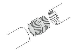
- Socket
-
Joints that connect to the external threads of a pipe.
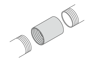
- Nipple
-
Joints that connect to the internal threads of a pipe.
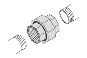
- Union
-
Joints that connect to the external threads of two pipes.
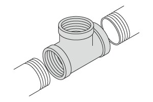
- T
-
Joints that connect to the external threads of two pipes to create a T-shaped branch for connecting a third pipe.
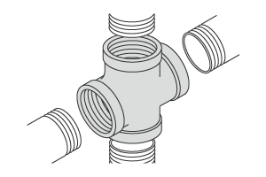
- Cross
-
Joints that connect to the external threads of four pipes to create a 4-way branch.
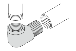
- Elbow
-
Joints that connect to the external threads of two pipes to create a 90-degree bend.
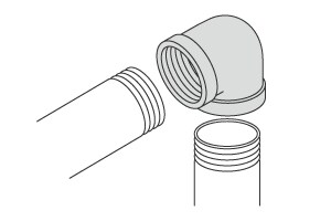
- Street elbow
-
Joints that connect to the external threads of one pipe and the internal threads of another pipe to create a 90-degree bend.
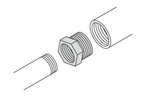
- Bushing
-
Joints that connect to the internal threads of one pipe and the external threads of another pipe with a different diameter. The internal threads of the pipe with the larger diameter are connected to the external threads of the pipe with the smaller diameter.
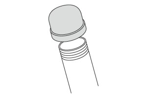
- Cap
-
Joints that connect to the external threads of a pipe to create an end cap.
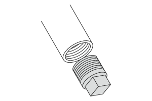
- Plug
-
Joints that connect to the internal threads of a pipe to create an end plug.
Types of valves
- Globe valve
-
Globe valves have a spherical valve housing and is sometimes called a stop valve. Fluid flows along an S-shaped path that is stopped by a valve body that is pressed against the gap in the centre. Opening and closing the valve requires turning the handle, which takes longer than other methods but allows for flow rate adjustments. This type is commonly used in water faucets.
Closed 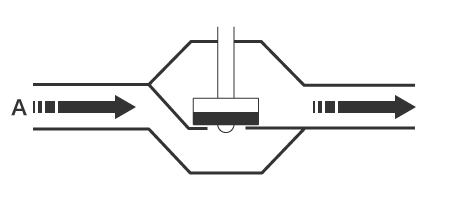
Open 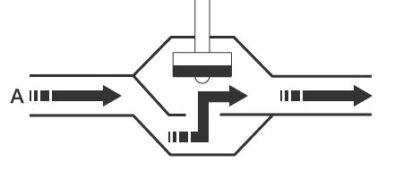
A: Fluid flow - Gate valve
-
Gate valves use a plate-shaped valve body that vertically divides the flow channel to stop the flow. These valves are used only to open or close the flow path and do not allow for flow rate adjustments. Opening and closing the valve requires turning the handle, which can take longer than other methods, and the vertical dimension of the valve is larger than that of other valve types. Gate valves are commonly used to stop the flow of water in water drainage mains and plant piping.
Closed 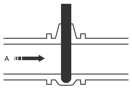
Open 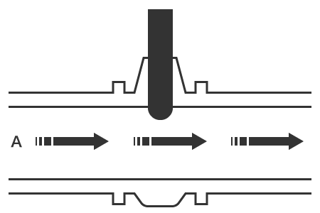
A: Fluid flow - Ball valve
-
Ball valves include a ball-shaped valvebody that rotates inside the valve housing to open or close the flow channel. The flow channel is opened when the through-hole is oriented along the flow path, and closed when it is oriented at a right angle to the flow path. Because the lever only needs to be rotated 90 degrees, opening and closing ball valves can be done quickly, and the straight flow path created ensures low resistance characteristics. This type of valve is commonly used as a main gas valve.
Closed 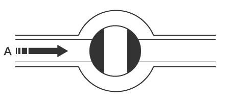
Open 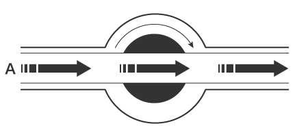
A: Fluid flow - Butterfly valve
-
Butterfly valves include a disc-shaped valve body in the valve housing that is rotated 90 degrees to open or close. Not only can the valve be opened or closed quickly, but these valves also offer excellent flow rate adjustment. The structure is also simple and does not require much installation space, making it commonly used in various situations.
Closed 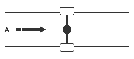
Open 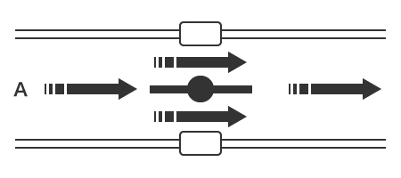
A: Fluid flow
Piping connection methods
- Threaded
-
Joints and valves that are screwed into a pipe can be divided into two categories: those with tapered threads and those with parallel threads. These types are mainly used for small-diameter, low-pressure piping at normal temperatures.
Tapered thread 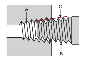
- A: Female thread
- B: Male thread
- C: Taper
Parallel thread 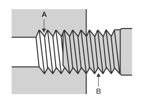
- A: Female thread
- B: Male thread
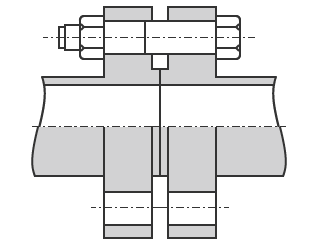
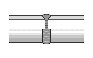
- Flanged
- With a flanged connection, the connection points are secured together using nuts and bolts. This type of connection can be used in a wide range of applications, including both small and large diameters as well as low and high pressures.
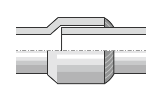
- Socket welded
- Socket welded connections are formed by inserting one pipe into the female connection of a joint or valve and welding the two together. This type of connection is used for high-temperature, high-pressure applications to help prevent leakage.
- Butt welded
- Butt welding secures the pipe and the joint or valve by welding the ends together. To ensure a strong weld, the ends are bevelled first. This type of connection is used for high-temperature, high-pressure applications to help prevent leakage.
Typical piping materials
- Iron pipes (black)
- Black iron pipes can be used for water, oil, steam, air, and various other fluids.
- Iron pipes (white)
- White iron pipes are hot dip galvanised to help prevent rust and corrosion.
- Brass
- Brass is a gold-coloured alloy of copper and zinc. One common use for this material is water piping for flushable toilets.
- Bronze
- This dull gold-coloured material is an alloy of copper, tin, zinc, lead, and other materials. Bronze is stronger, harder, and more resistant to rust than brass.
- Stainless steel (SUS)
- Stainless steel is a popular material for its excellent corrosion and heat resistance as well as durability.
- Polyvinyl chloride (PVC)
- This grey material is inexpensive and offers excellent versatility and strength. PVC is commonly used as water supply and drainage piping.
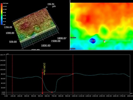
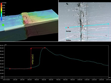
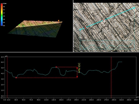
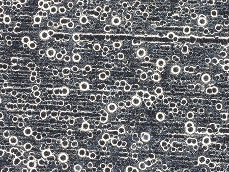
Observation and measurement examples of piping, joints, and valves using a digital microscope
The latest examples of observation and measurement of piping, joints, and valves using KEYENCE’s VHX Series 4K Digital Microscope are introduced below.
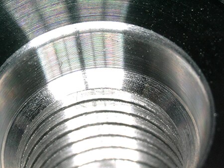
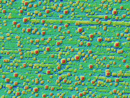
The glare removal and depth composition functions enable clear observation of the inner walls of joints with all surfaces in focus.
VH-Z00, 30×, ring illumination
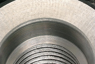
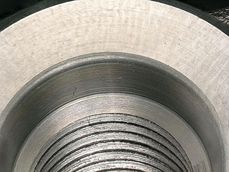
The VH-Z00 can be used to check for burrs on the inner wall of a valve at an observation distance of 95 mm.
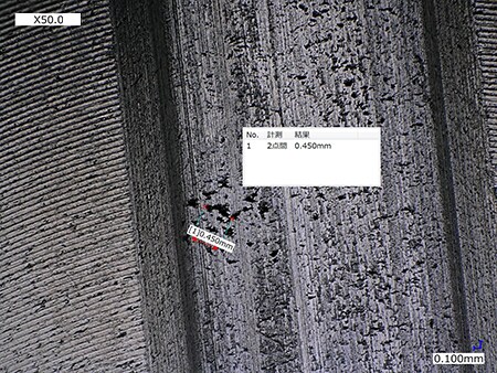
VH-Z00, 50×, multi-lighting illumination
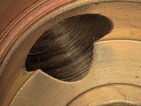
The multi-lighting function can be used to visualise even minute surface scratches.
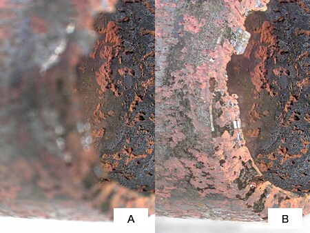
ZS-20, 30×, ring illumination image
- A: Without depth composition
- B: With depth composition