Programmable Controller
KV-5000/3000 series
Specs Programmable Controller KV-5000/3000 series
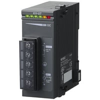
CPU unit
|
Model |
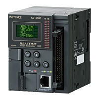
KV-5500 *1 |
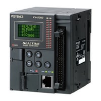
KV-5000 *1 |
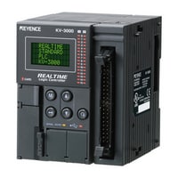
KV-3000 |
|||
|
Image |
|
|
|
|||
|
Type |
CPU Unit |
|||||
|
General specifications |
Power voltage |
24 VDC (±10%) |
||||
|
Operating ambient temperature |
0 to +50°C (with no frost)*2*3 |
0 to +50°C (no freezing)*4*8 |
||||
|
Operating ambient humidity |
10 to 95%RH (no condensation)*4 |
|||||
|
Ambient temperature for storage |
-20 to +70°C*4 |
|||||
|
Storage relative humidity |
10 to 95 % RH (No condensation)*2*5 |
|||||
|
Operating environment |
Without dust and corrosive gas |
|||||
|
Altitude |
2,000 m or less |
|||||
|
Noise immunity |
1,500 Vp-p or more, pulse width: 1 µs, 50 ns (by way of a noise simulator) |
|||||
|
Withstand voltage |
1,500 VAC for 1 minute between the power supply terminal and the I/O terminals and between all the external terminals and the case |
|||||
|
Insulation resistance |
50 MΩ or more (tested with a 500 VDC megger, between the power supply terminal and the I/O terminals and between all the external terminals and the case) |
|||||
|
Shock resistance |
Acceleration 150 m/s2, Operation time 11 ms, twice in each of the X, Y and Z directions |
|||||
|
Overvoltage category |
II (when using KV-U7) |
|||||
|
Pollution degree |
2 |
|||||
|
Vibration resistance |
Intermittent vibration |
Frequency 5 to 9 Hz |
Half amplitude: 3.5 mm*6 |
|||
|
Frequency 9 to 150 Hz |
Acceleration: 9.8 m/s2*6 |
|||||
|
Continuous vibration |
Frequency 5 to 11 Hz |
Half amplitude: 1.75 mm*6 |
||||
|
Frequency 9 to 150 Hz |
Acceleration: 4.9 m/s2*6 |
|||||
|
Performance specifications |
Arithmetic control mode |
Stored program mode |
||||
|
I/O control mode |
Refresh mode |
|||||
|
Program language |
Expanded ladder, KV Script, mnemonic |
|||||
|
Number of commands |
Basic instruction: 81 classes, 182 instructions |
|||||
|
Instruction execution speed |
Basic instruction: Min. 10 ns |
|||||
|
Program capacity |
Approx. 260k steps |
Approx. 160k steps |
||||
|
Maximum number of units to be installed |
16 units (48 units when expansion units are connected) |
|||||
|
Maximum number of I/O points |
Maximum 3,096 points for expansion (KV-EB1S/KV-EB1R: When 2 units are expanded, 64-point I/O unit is used) |
|||||
|
Bit device |
Input relay R |
Total 16,000 points 1 bit |
||||
|
Output relay R |
||||||
|
Internal auxiliary relay R |
||||||
|
Link relay B |
16,384 points 1 bit |
|||||
|
Internal auxiliary relay MR |
16,000 points 1 bit |
|||||
|
Latch relay LR |
||||||
|
Control relay CR |
640 points 1 bit |
|||||
|
Word device |
Timer T |
4,000 points 32 bits |
||||
|
Counter C |
||||||
|
Data memory DM |
65,535 points 16 bits |
|||||
|
Expansion data memory EM |
||||||
|
File register |
Memory bank switching mode FM |
32,768 points × 4 memory banks 16 bits |
||||
|
Dial mode ZF |
131,072 points 16 bits |
|||||
|
Link register W |
16,384 points 16 bits |
|||||
|
Temporary data memory TM |
512 points 16 bits |
|||||
|
High-speed counter CTH |
2 points 32 bits |
|||||
|
4 points 32 bits (2 points for one high-speed counter) |
||||||
|
Index register Z |
12 points 32 bits |
|||||
|
Control memory CM |
6,000 points 16 bits |
|||||
|
Positioning pulse output |
2 points (maximum output frequency: 100 kHz) |
|||||
|
CPU unit I/O |
Input: 16 points, output: 8 points |
|||||
|
Power failure hold function |
Program memory |
Flash ROM can be rewritten 100,000 times |
||||
|
Device |
5 years (operating ambient temperature of 25°C in the power failure hold mode)*7 |
|||||
|
Self-diagnosis function |
CPU abnormal, RAM abnormal, other |
|||||
|
Internal current consumption |
CPU unit: 320 mA or less |
|||||
|
Weight |
CPU unit: approx. 320 g |
CPU unit: approx. 300 g |
||||
|
*1 This product is not available for sale in China and cannot be ordered for shipment to China. |
||||||
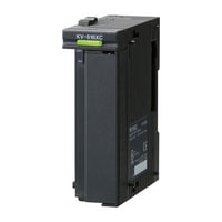
AC power unit
|
Model |
KV-U7 |
|||
|
Image |
|
|||
|
Type |
AC power unit |
|||
|
Input supply voltage |
100 to 240 VAC ±10 % (50/60 Hz) |
|||
|
Output voltage |
24 VDC ±10 % |
|||
|
Output capacity |
1.8 A |
|||
|
Power consumption |
135 VA or less |
|||
|
Momentary stop time |
10 ms or less |
|||
|
Starting time |
2 sec. or less |
|||
|
Weight |
Approx. 190 g |
|||
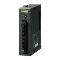
Input unit
|
Model |
KV-B16XC |
KV-C32XC |
KV-C64XC |
|||
|
Image |
|
|
|
|||
|
Type |
Input unit |
|||||
|
External connection mode |
Removable terminal block |
Connector (MIL specification)*3 |
||||
|
Input |
Number of inputs |
16 points |
32 points |
64 points |
||
|
Input mode |
24 VDC mode, 5 VDC mode |
24 VDC mode*4 |
||||
|
Max. input voltage |
26.4 VDC |
|||||
|
Rated input voltage |
24 VDC mode: 24 VDC 5.3 mA, 5 VDC mode: 5 VDC 1 mA |
24 VDC 4.1 mA |
||||
|
Min. ON voltage |
24 VDC mode: 19 V, 5 VDC mode: 3.5 V |
19 V |
||||
|
Max. OFF current |
24 VDC mode: 1.5 mA |
1.5 mA |
||||
|
Max. OFF voltage |
5 VDC mode: 1.5 V |
- |
||||
|
Common point mode |
16 points/1 common point (2 terminals)*1 |
32 points/1 common point (2 terminals)*1 |
32 points/1 common point (4 terminals)*5 |
|||
|
Input time constant |
[Input time constant setting 25 µs] OFF to ON: TYP 25 µs/MAX 65 µs, ON to OFF: TYP 75 µs/MAX 120 µs |
|||||
|
Input impedance |
4.3 kΩ |
5.6 kΩ |
||||
|
Internal current consumption |
15 mA or less |
25 mA or less |
||||
|
Weight |
Approx. 120 g |
Approx. 110 g |
Approx. 140 g |
|||
|
*1 Even though KV-B16XC and KV-C32XC have two common points, they are the same internally. |
||||||
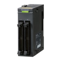
Output unit
|
Model |
KV-B16RC |
KV-B8RC |
KV-B16TD |
KV-B16TCP |
|||
|
Image |
|
|
|
|
|||
|
Type |
Output unit |
||||||
|
External connection mode |
Removable terminal block |
||||||
|
Output |
Number of outputs |
16 points |
8 points |
16 points |
|||
|
Output form |
Relay |
MOS-FET (sink) (with overcurrentprevention function) |
Transistor (source) |
||||
|
Rated load |
250 VAC/30 VDC 2 A (8 A/1 common point) |
250 VAC/30 VDC 2 A |
30 VDC 0.3 A |
30 VDC 0.2 A |
|||
|
Leak current at OFF |
- |
100 µA or less |
|||||
|
Residual voltage at ON |
0.5 V or less |
||||||
|
ON resistance |
50 mΩ or less |
- |
|||||
|
Common point mode |
8 points/1 common points |
Independent |
16 points/1 common point (2 terminals)*1 |
||||
|
Operating time |
OFF to ON/ON to OFF: 10 ms or less |
OFF to ON: 100 µs or less、ON to OFF: 300 µs or less |
OFF to ON: 10 µs or less、ON to OFF: 200 µs or less |
||||
|
Internal current consumption |
120 mA or less |
65 mA or less |
45 mA or less |
35 mA or less |
|||
|
Weight |
Approx. 190 g |
Approx. 160 g |
Approx. 130 g |
||||
|
*1 Although KV-B16TD, KV-C32TD, KV-B16TCP, and KV-C32TCP have two points, they are the same internally. |
|||||||

Output unit
|
Model |
KV-C32TD |
KV-C32TCP |
KV-C64TD |
KV-C64TCP |
|||
|
Image |
|
|
|
|
|||
|
Type |
Output unit |
||||||
|
External connection mode |
Connector (MIL specification)*1 |
||||||
|
Output |
Number of outputs |
32 points |
64 points |
||||
|
Output form |
MOS-FET (sink) (with overcurrentprevention function) |
Transistor (source) |
MOS-FET (sink) (with overcurrentprevention function) |
Transistor (source) |
|||
|
Rated load |
30 VDC 0.2 A |
||||||
|
Leak current at OFF |
100 µA or less |
||||||
|
Residual voltage at ON |
0.5 V or less |
||||||
|
ON resistance |
- |
||||||
|
Common point mode |
32 points/1 common point (2 terminals)*2 |
64 points/1 common point (4 terminals)*3 |
|||||
|
Operating time |
OFF to ON: 100 µs or less、ON to OFF: 300 µs or less |
OFF to ON: 10 µs or less、ON to OFF: 200 µs or less |
OFF to ON: 150 µs or less、ON to OFF: 300 µs or less |
OFF to ON: 50 µs or less、ON to OFF: 200 µs or less |
|||
|
Internal current consumption |
65 mA or less |
55 mA or less |
120 mA or less |
100 mA or less |
|||
|
Weight |
Approx. 100 g |
Approx. 140 g |
|||||
|
*1 Connectors for connector-type I/O units are not included. MIL34-pin slender connector kit OP-42224 and MIL34-pin connector kit OP-23139 are available separately. |
|||||||
I/O unit
|
Model |
KV-B8XTD |
KV-C16XTD |
KV-C32XTD |
|||
|
Image |
|
|
|
|||
|
Type |
I/O unit |
|||||
|
External connection mode |
Removable terminal block |
Connector (MIL standard)*2 |
||||
|
Input |
Number of inputs |
8 points |
16 points |
32 points |
||
|
Input mode |
24 VDC mode, 5 VDC mode |
24 VDC mode*3 |
||||
|
Max. input voltage |
26.4 VDC |
|||||
|
Rated input voltage |
24 VDC mode: 24 VDC 5.3 mA, 5 VDC mode: 5 VDC 1 mA |
24 VDC 4.1 mA |
||||
|
Min. ON voltage |
24 VDC mode: 19 V, 5 VDC mode: 3.5 V |
19 V |
||||
|
Max. OFF current |
24 VDC mode: 1.5 mA |
1.5 mA |
||||
|
Max. OFF voltage |
5 VDC mode: 1.5 V |
- |
||||
|
Common point mode |
8 points/1 common point (1 terminal) |
16 points/1 common point (1 terminal) |
32 points/1 common point (2 terminals)*4 |
|||
|
Input time constant |
25 µs/300 µs*1/1 ms/10 ms |
|||||
|
Input impedance |
4.3 kΩ |
5.6 kΩ |
||||
|
Output |
Number of outputs |
8 points |
16 points |
32 points |
||
|
Output form |
MOS-FET (N ch) (with an overcurrent-proof function) |
|||||
|
Rated load |
30 VDC 0.3 A |
30 VDC 0.2 A |
||||
|
Leak current at OFF |
100 µA or less |
|||||
|
Residual voltage at ON |
0.5 V or less |
|||||
|
Common point mode |
8 points/1 common point (1 terminal) |
16 points/1 common point (1 terminal) |
32 points/1 common point (2 terminals)*4 |
|||
|
Operating time |
OFF to ON: 100 µs or less, ON to OFF: 300 µs or less |
OFF to ON: 150 µs or less, ON to OFF: 300 µs or less |
||||
|
Internal current consumption |
30 mA or less |
40 mA or less |
65 mA or less |
|||
|
Weight |
Approx. 130 g |
Approx. 110 g |
Approx. 130 g |
|||
|
*1 Setup is only possible when KV-7500/7300/5500/5000/3000 is connected. When KV-1000/700 is connected, selection is not possible. |
||||||
A/D and D/A conversion unit
|
Model |
KV-AD40V |
KV-AD40 |
KV-DA40V |
KV-DA40 |
|||
|
Image |
|
|
|
|
|||
|
Type |
A/D conversion unit |
D/A conversion unit |
|||||
|
Analogue I/O point |
4 points (differential input) |
4 points |
|||||
|
Analogue I/O range (resolution) |
Voltage |
-10 to +10 V (0.5 mV 1/40,000) |
-10 to +10 V (2.5 mV 1/8,000) |
-10 to +10 V (0.5 mV 1/40,000) |
-10 to +10 V (2.5 mV 1/8,000) |
||
|
Input current |
0 to 20 mA (1 µA 1/20,000) |
0 to 20 mA (5 µA 1/4,000) |
0 to 20 mA (1 µA 1/20,000) |
0 to 20 mA (5 µA 1/4,000) |
|||
|
Input impedance |
Voltage: 5 MΩ, Current: 250 Ω |
Voltage: 1 MΩ, Current: 250 Ω |
- |
||||
|
Conversion speed |
25 µs/ch*1 |
80 µs/ch |
25 µs/ch |
80 µs/ch |
|||
|
Conversion precision |
25 °C ±5 °C |
Voltage: ±0.1 % of F.S.*2, Current: ±0.1 % of F.S. |
Voltage: ±0.2 % of F.S., Current: ±0.2 % of F.S. |
Voltage: ±0.1 % of F.S., Current: ±0.2 % of F.S. |
Voltage: ±0.2 % of F.S., Current: ±0.2 % of F.S. |
||
|
0 to 50 °C |
Voltage: ±0.2 % of F.S.*3, Current: ±0.2 % of F.S. |
Voltage: ±0.3 % of F.S., Current: ±0.3 % of F.S. |
Voltage: ±0.4 % of F.S., Current: ±0.4 % of F.S. |
||||
|
Insulation mode |
Between unit and CPU: Photocoupler insulation, non-insulation between channels |
||||||
|
Absolute max. input |
Voltage: ±15 V, Current: 30 mA |
||||||
|
Min. load resistance |
Voltage: 1 kΩ |
||||||
|
Max. load resistance |
Current: 500 Ω |
Current: 400 Ω |
|||||
|
Internal current consumption |
140 mA or less |
110 mA or less |
170 mA or less |
230 mA or less |
|||
|
Weight |
Approx. 150 g |
||||||
|
*1 When temperature drift correction is used, temperature drift correction time of 25 µs is added regardless of the number of channels used. |
|||||||
High-precision A/D conversion unit
|
Model |
KV-AD40G |
|||
|
Image |
|
|||
|
Type |
High-precision A/D conversion unit |
|||
|
Analogue input point |
4 points (differential input) |
|||
|
Analogue input range (resolution) |
Voltage |
-10 to 10 V (0.33 mV 1/60,000) |
||
|
Input current |
0 to 20 mA (0.67 µA 1/30,000) |
|||
|
Input resistance |
Voltage: 5 MΩ, Current: 250 Ω |
|||
|
Conversion speed |
80 µs/2 ch, 160 µs/4 ch (the quickest 50 µs/2 ch, 100 µs/4 ch when data buffer function is used) |
|||
|
Conversion precision |
25 °C |
Voltage: ±0.05 % of F.S., Current: ±0.05 % of F.S. |
||
|
0 to 50 °C |
Voltage: ±0.1 % of F.S., Current: ±0.1 % of F.S. |
|||
|
Insulation mode |
Unit - Between CPUs: Photocoupler insulation, |
|||
|
Absolute max. input |
Voltage: ±15 V, Current: 30 mA |
|||
|
External trigger input |
Number of input points: 1, Input signal: NPN open collector, no-voltage contact signal |
|||
|
Data buffering function |
Data buffering period: 50 µs to 3 s, buffering data quantity: maximum 10000 words/ch |
|||
|
Special functions |
Scaling, average processing (specification of the number of times, time specification, moving average, primary delay filter), |
|||
|
Internal current consumption |
220 mA or less |
|||
|
Weight |
Approx. 190 g |
|||
|
*1 Not insulated between CH_A0 and CH_A1 or between CH_B0 and CH_B1 |
||||
A/D and D/A conversion unit
|
Model |
KV-AM40V |
|||
|
Image |
|
|||
|
Type |
A/D and D/A conversion unit |
|||
|
Analogue I/O point |
Input: 2 points (differential input), Output: 2 points |
|||
|
Analogue I/O range (resolution) |
Voltage |
-10 to +10 V (1.25 mV 1/16,000) |
||
|
Input current |
0 to 20 mA (2.5 µA 1/8,000) |
|||
|
Input resistance |
Voltage: 5 MΩ, Current: 250 Ω |
|||
|
Conversion speed |
80 µs/ch*2*3 |
|||
|
Conversion precision |
±0.2 % of F.S. (25 °C ±5 °C), ±0.4 % of F.S. (0 to 50 °C)*4 |
|||
|
Insulation mode |
Between unit and CPU: Photocoupler insulation, Among channels: Not insulated |
|||
|
Absolute max. input |
Voltage: ±15 V, Current: 30 mA |
|||
|
Min. load resistance |
Voltage: 1 kΩ |
|||
|
Max. load resistance |
Current: 600 Ω |
|||
|
Internal current consumption |
140 mA or less |
|||
|
Weight |
Approx. 150 g |
|||
|
*1 Analogue output is not available within the range of -5 to +5 V. |
||||
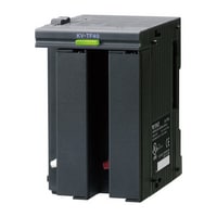
Multi-input PID temperature control unit
|
Model |
KV-TF40 |
|||
|
Image |
|
|||
|
Type |
Multi-input PID temperature control unit |
|||
|
Memory elements |
EEPROM rewritable one million times |
|||
|
Number of temperature input points |
4 ch |
|||
|
Input |
Thermocouple/Platinum temperature measuring resistor*1 |
|||
|
Temperature sensor types |
Thermocouple: K, J, T, E, R, B, N, S, W5Re/W26Re |
|||
|
Indicated accuracy |
±0.3 % of F.S. ±1 digit (+25 °C), ±0.7 % of F.S. ±1 digit (0 to +50 °C) |
|||
|
Cold junction correction precision |
±1 °C |
|||
|
Sampling period |
125 ms/ch (500 ms/4 ch) |
|||
|
Control period |
1 to 100 sec. |
|||
|
Operating mode |
PID control (with auto-tuning and 3 mode stabiliser function installed) |
|||
|
Tuning mode |
PID auto-tuning mode |
|||
|
Control output |
transistor (sink) |
|||
|
Alarm output |
transistor (sink)*2 |
|||
|
Alarm mode |
Absolute value upper limit, absolute value lower limit, deviation upper limit, deviation lower limit, |
|||
|
Output |
Rated load |
30 VDC 100 mA or less |
||
|
Leak current at OFF |
100 µA or less |
|||
|
Residual voltage at ON |
1.5 V or less |
|||
|
Current sensor (CT) input |
4 ch*4 |
|||
|
Current measurement precision |
Larger of ±5 % of an input value and ±2 A of an input value |
|||
|
Insulation mode |
Between inputs and outputs: Photocoupler and transformer insulation, |
|||
|
Other functions |
Heater wire breaking alarm, control loop wire breaking alarm, measured value bias, |
|||
|
Internal current consumption |
210 mA or less |
|||
|
Weight |
Approx. 270 g |
|||
|
*1 Can be set for each channel. |
||||
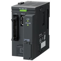
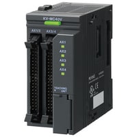
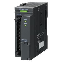
Positioning/Motion Unit
|
Model |
KV-ML16V |
KV-MC40V |
KV-MC20V |
|||
|
Image |
|
|
|
|||
|
Type |
Positioning/Motion unit |
|||||
|
Number of control axes |
16 axes (total including a virtual axis) |
4 axes + 1 axis (virtual axis) |
2 axes |
|||
|
Built-in device |
[16 axes in use] |
Relay: 1280 points (80 ch), Data memory: 90 words (high speed) /582 words (simple) |
Relay: 896 points (56 ch), Data memory: 54 words (high speed)/402 words (simple) |
|||
|
Output format |
MECHATROLINK-II |
Differential line driver output (switchable among 1-pulse method, 2-pulse method, and A/B-phase method) |
||||
|
Connectable CPU units |
KV-8000/7500/7300/5500/5000/3000 |
|||||
|
Max. output pulse |
- |
4 MHz |
||||
|
Control mode |
Position control, Torque control, Speed control, ML-II command, I/O control |
Position control |
||||
|
Control period |
0.5 ms (up to 2 axes), 1.0 ms (up to 4 axes), 1.5 ms (up to 6 axes), |
1.0 ms |
||||
|
External interface |
Input: Photocoupler input, Output: Open collector output (30 VDC 50 mA) |
Input: Photocoupler input, Output: Open collector output (30 VDC 50 mA) |
||||
|
Input time constant |
Each input is set in 11 stages for each block |
|||||
|
Axis control function execution method |
Ladder program, motion flow |
|||||
|
Motion flow |
Program capacity |
768 KB |
||||
|
Max. number of blocks |
A total of 256 blocks in all flows |
|||||
|
Max. number of flows |
32 |
|||||
|
Number of simultaneous activities |
Number of connectable axes × 2 |
|||||
|
Position unit |
mm, deg (angle), PLS (pulse count), decimal point position from 0 to 9 digits, unit conversion function available |
|||||
|
Cumulative address |
-2,147,483,648 to +2,147,483,647 instruction units |
|||||
|
Positioning control |
Positioning mode |
Absolute value/relative value |
||||
|
Position setting range |
-2,147,483,648 to +2,147,483,647 instruction units |
|||||
|
Interpolation |
Straight-line interpolation (up to 16 axes), arc interpolation, helical interpolation |
|||||
|
Single operation address |
-2,147,483,648 to +2,147,483,647 instruction units |
|||||
|
Acceleration/deceleration curve |
Straight-line, SIN, Bezier |
|||||
|
Acceleration/deceleration time |
0 to 65,535 ms |
|||||
|
Start-up time |
Independent/interpolation: 2 to 3 control periods (When the 1st axis is activated) |
Independent: 500 to 600 µs, Interpolation (straight-line 2 axes): 600 to 700 µs, Interpolation (arc 2 axes): 700 to 800 µs, |
||||
|
M-code |
1 to 65,000, WITH/AFTER mode |
|||||
|
Sensor positioning |
External input - based switching control from speed to position |
|||||
|
Number of points |
800 points/axis |
|||||
|
Synchronisation control |
Input |
Counter (KV-MX1 required), instruction coordinates, current coordinates (KV-ML16V only) |
||||
|
Clutch |
Select from direct, slide, and follow-up |
|||||
|
Cam |
Resolution: 2,048 to 32,768, Amount of data: 4 to 64 (Number changes according to the resolution) |
Resolution: 2048 to 32768, Amount of data: 4 to 64 (Number changes according to the resolution) |
||||
|
Contact output |
16 points (including 8 external output points) × 2 |
|||||
|
Correction during operation |
Correction via auxiliary input, phase correction, and lead angle correction |
|||||
|
Fine control |
Fine data work area |
8 MB |
||||
|
Built-in ROM capacity |
512 KB |
|||||
|
Number of settings |
Built-in ROM: 100, SD memory card: 1000 |
|||||
|
Data capacity of one setting |
Built-in ROM: 512 KB, SD memory card: 8 MB (KV-MX1 is required) |
|||||
|
Origin return |
Origin return method |
Origin sensor edge/midpoint, push origin return, Dog type ("With Z phase" or "Without Z phase" can be selected) |
Origin sensor edge/midpoint, push origin return, Dog type ("With Z phase" or "Without Z phase" can be selected), data set type, no limit switch |
|||
|
Speed control |
Speed instruction range |
-100,000 to 100,000 (× 0.01 min-1) |
- |
|||
|
Torque control |
Torque instruction range |
-80,000 to 80,000 (× 0.01 %) |
||||
|
JOG/inching |
Inching (The number of pulses can be specified), JOG (high speed/low speed) |
|||||
|
Teaching |
Current coordinate teaching and teaching from the counter current value are supported |
|||||
|
Memory data |
Point parameters 800 points (each axis), synchronisation parameters (each axis), fine setting (built-in ROM: 512 KB, expandable with a SD card), |
|||||
|
High-speed counter |
When KV-MX1 is connected: INC 4 ch/ABS Grey, residual Grey, binary 2 ch (switched, based on settings), Max. 6.4 MHz (2-phase, 4 multiplication) |
|||||
|
5-V power output |
- |
5 V ±5%, Max. 100 mA (total value) |
||||
|
Output display |
Error status/MECHATROLINK-II communication status |
Error status/Pulse output status |
||||
|
Self-diagnosis function |
Diagnosis can be made through hardware error, various parameter errors, error number, and error messages |
|||||
|
Parameter setting |
Parameters can be set from KV-HPD1, “KV STUDIO,” and ladder programs |
|||||
|
Data backup |
Coordinates and error/warning history backup, parameter settings backup via flash ROM, 100,000 times switching |
|||||
|
Internal current consumption |
Main unit: 200 mA or less, external I/O: 120 mA or less |
Main unit: 180 mA or less, external I/O: 130 mA or less |
Main unit: 120 mA or less, external I/O: 80 mA or less |
|||
|
Weight |
Approx. 220 g |
Approx. 225 g |
Approx. 170 g |
|||
Function extension unit
|
Model |
KV-MX1 |
|||
|
Image |
|
|||
|
Type |
Function extension unit |
|||
|
Supported unit |
KV-ML16V/KV-MC40V/KV-MC20V |
|||
|
Input frequency |
Max. 6.4 MHz (2-phase, 4 multiplication) |
|||
|
Number of counter points |
INC: 4 points, ABS: 2 points (set by "KV STUDIO") |
|||
|
Maximum connectable number of units |
One unit per positioning/motion unit, the right side only |
|||
|
Internal current consumption |
Main unit: 30 mA or less, external I/O: 100 mA or less |
|||
|
Weight |
Approx. 160 g |
|||
Communication positioning unit
|
Model |
KV-LH20V |
|||
|
Image |
|
|||
|
Type |
Communication positioning unit |
|||
|
Control period |
Positioning (PTP: point to point) control (independent) Speed control*1 |
|||
|
Number of control axes |
1 to 8 |
|||
|
Transmission specification |
Transmission rate |
9600, 14400, 19200, 28800, 38400, 57600, 76800, 115200, 230400 bps |
||
|
Transmission distance |
Total extension: 1,200 m max.*2 |
|||
|
Communication interface |
Communication standard: RS-485 (2-wire type), Communication protocol: Modbus RTU |
|||
|
Connectable CPU units |
KV-8000/7500/7300/5500/5000/3000 |
|||
|
Positioning control |
Number of points |
64 points/axis*3 |
||
|
Internal current consumption |
120 mA or less |
|||
|
Weight |
Approx. 110 g |
|||
|
*1 Only when a stepping motor from ORIENTAL MOTOR Co., Ltd. is used. |
||||
Positioning unit
|
Model |
KV-H20S |
KV-H40S |
|||
|
Image |
|
|
|||
|
Type |
Positioning unit |
||||
|
Control period |
Positioning (PTP: point to point) control (independent, straight-line interpolation) |
||||
|
Number of control axes |
2-axes/unit, independent 2-axes Interpolation 2-axes (straight line) |
4-axes/unit, independent 4-axes Interpolation 2- to 4-axes (straight line) |
|||
|
Connectable CPU units |
KV-8000/7500/7300/5500/5000/3000 |
||||
|
Starting time |
Independent operation: 1.5 ms, Straight-line interpolation operation: 1.8 ms |
||||
|
Positioning control |
Position setting range |
±99,999,999 (pulse, mm, degree) Incremental, absolute Coordinate control range (-2,147,483,648 to 2,147,483,647) |
|||
|
Acceleration/deceleration rate |
1 to 65,000 (p/s/ms, mm/s/ms, deg/s/ms) (However, when 65,000 is set, acceleration/deceleration is applied immediately.) |
||||
|
Number of points |
400 points/axis |
200 points/axis |
|||
|
Acceleration/deceleration mode |
Straight line, sine |
||||
|
Speed control |
Speed instruction range |
1 to 1,000,000 p/s |
|||
|
Pulse output state |
Differential line driver output (switching between 1 pulse and 2 pulses) |
||||
|
Memory backup |
Flash ROM |
||||
|
Other functions |
Test operation function, Sensor interrupt-stopping function, Continuous action, Approach rotation control |
||||
|
Internal current consumption |
120 mA or less |
130 mA or less |
|||
|
Weight |
Approx. 150 g |
Approx. 200 g |
|||
Synchronisation and cam motion unit
|
Model |
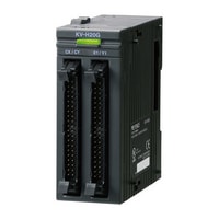
KV-H20G |
|||
|
Image |
|
|||
|
Type |
Synchronisation and cam motion unit |
|||
|
Control period |
Positioning (PTP: point to point) control (independent, straight-line interpolation) |
|||
|
Number of control axes |
2 axes/unit, interpolation 2-axes (straight line, arc) |
|||
|
Connectable CPU units |
KV-8000/7500/7300/5500/5000/3000 |
|||
|
Starting time |
Independent operation: 1.5 ms, Straight-line operation: 1.8 ms, Arc interpolation operation: 2.1 ms |
|||
|
Positioning control |
Position setting range |
±99,999,999 (pulse, mm, degree) Incremental, absolute Coordinate control range (-2,147,483,648 to 2,147,483,647) |
||
|
Acceleration/deceleration rate |
1 to 65,000 (p/s/ms, mm/s/ms, deg/s/ms) (However, when 65,000 is set, acceleration/deceleration is applied immediately.) |
|||
|
Number of points |
400 points/axis |
|||
|
Acceleration/deceleration mode |
Straight line, sine |
|||
|
Speed control |
Speed instruction range |
1 to 1,000,000 p/s |
||
|
High-speed counter |
24-bit-symbol 2-phase 2 ch (INC) /max. 12-bit (ABS), Grey code, residual Grey code, binary conversion |
|||
|
Pulse output state |
Differential line driver output (switching between 1 pulse and 2 pulses) |
|||
|
Memory backup |
Flash ROM |
|||
|
Other functions |
Test operation function, Sensor interrupt-stopping function, Continuous action, Approach rotation control |
|||
|
Internal current consumption |
130 mA or less |
|||
|
Weight |
Approx. 200 g |
|||
High-speed counter unit
|
Model |
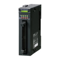
KV-SC20V |
|||
|
Image |
|
|||
|
Type |
High-speed counter unit |
|||
|
Input frequency |
1 MHz (4 MHz during 2-phase, 4 times multiplication) |
|||
|
Counting range |
32 bits |
|||
|
Number of channels |
2 ch |
|||
|
Mode |
Input selection |
External terminal (CH0, CH1), internal clock (1 µs, 10 µs, 100 µs), other CH coincidence output |
||
|
Input mode |
1-pulse with/without direction, 2-pulse addition/subtraction operation, 2-phase 1X/2X/4X |
|||
|
Counting operation mode |
Up-down counting mode, Enable counting mode, Preset counting mode, |
|||
|
Counting mode |
Linear, ring |
|||
|
Frequency, revolution counter operation mode |
Frequency counting mode, revolution counter B mode (1-revolution time measurement) |
|||
|
Connectable CPU units |
KV-8000/7500/7300/5500/5000/3000 |
|||
|
Input |
Count input |
A-phase/B-phase/Z-phase (preset), 3 points for each channel, 6 points in total |
||
|
Control input |
Enable (also used for input capture) input, 1 point for each channel, 2 points in total 12 to 24 V DC input possible, photocoupler insulatio |
|||
|
Output |
Comparator coincidence output |
2 points for each channel, 4 points in total, photocoupler insulation |
||
|
Input capture function |
By external input (max. 4 points) |
|||
|
Input filter function |
Input time constant switching (4 types of counting/7 types of control) |
|||
|
Preset function |
Possible to select from preset (Z-phase) input and internal relay-based rising edge/falling edge/level (only when an external input is used) |
|||
|
Internal current consumption |
95 mA or less |
|||
|
Weight |
Approx. 120 g |
|||
Serial communication unit
|
Model |
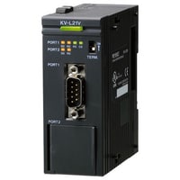
KV-L21V |
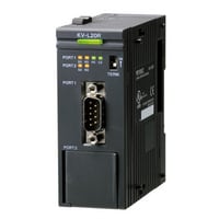
KV-L20R*2 |
|||
|
Image |
|
|
|||
|
Type |
Serial communication unit |
||||
|
Connection interface |
Port 1: RS-232C, Port 2: RS-232C/RS-422A/RS-485 (4 wires) /RS-485 (2 wires) switching |
||||
|
Transmission specification |
Transmission rate |
1,200, 2,400, 4,800, 9,600, 19,200, 38,400, 57,600, 115,200, 230,400 bps |
1,200, 2,400, 4,800, 9,600, 19,200, 38,400, 57,600, 115,200 bps |
||
|
Transmission method |
RS-232C/RS-422A/RS-485 (4 wires): Full duplex, RS-485 (2 wires): Half duplex |
RS-232C, RS-422A, RS-485 (4 wires): Full duplex RS-485 (2 wires): Half duplex |
|||
|
Transmission distance |
RS-232C: 15 m or less, RS-422A/RS-485 (4 wires) /RS-485 (2 wires): Total extension 1,200 m or less*1 |
RS-232C: 15 m or less, RS-422A, RS-485 (4 wires)/RS-485 (2 wires): Total extension 500 m or less |
|||
|
Internal current consumption |
120 mA or less |
||||
|
Weight |
Approx. 150 g |
Approx. 160 g |
|||
|
*1 When transmission speed is 230,400 bps, total extension will be 500 m or less. Transmission speed and transmission distance change according to connected devices. Check with the actual device. |
|||||
Ethernet unit
|
Model |
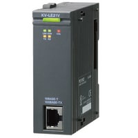
KV-LE21V *1 |
|||
|
Image |
|
|||
|
Type |
Ethernet Unit |
|||
|
PC application |
Number of sockets: TCP 8/UDP 0, Port No. 8,500 (set within the range of 1 to 65,535)*2 |
|||
|
Upper level link communication |
Number of sockets: TCP Total 15/UDP 1, Port No. 8,501 (set within the range of 1 to 65,535)*3*4 |
|||
|
MC protocol communication |
Number of sockets: TCP Total 15/UDP 1, Port No. 5,000 (set within the range of 1 to 65,535)*3*4*5 |
|||
|
VT3 connection |
Number of sockets: TCP 0/UDP 1, Port No. 8,502 (set within the range of 1 to 65,535) |
|||
|
KV socket communication |
Number of sockets: TCP/UDP Total 8, Port No. Any (set within the range of 1 to 65,535)*6 |
|||
|
FTP server |
Number of sockets: TCP 4, Port No. 20,21 |
|||
|
Clock data automatic adjustment |
Number of sockets: UDP 1, Port No. 123 |
|||
|
Mail send and receive (SMTP, POP3) |
Number of sockets: TCP 2, Port No. 25,110 |
|||
|
DNS |
Number of sockets: UDP 1, Port No. 53 |
|||
|
FTP Client |
Number of sockets: TCP 2, Port No. 25,110 (set within the range of 1 to 65,535) |
|||
|
Simple PLC Link |
Number of sockets: UDP 1, Port No. 5,001 (set within the range of 1 to 65,535) |
|||
|
Connectable CPU units |
KV-8000/7500/7300/5500/5000/3000 |
|||
|
Internal current consumption |
80 mA or less |
|||
|
Weight |
Approx. 120g |
|||
|
*1 This product is not available for sale in China and cannot be ordered for shipment to China. |
||||
FL-net unit
|
Model |
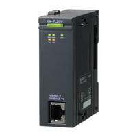
KV-FL20V |
|||
|
Image |
|
|||
|
Type |
FL-net unit |
|||
|
Connection interface |
IEEE802.3 compliant (CSMA/CD compliant) |
|||
|
Transmission specification |
Transmission rate |
Automatic switching to and from 10 Mbps/100 Mbps |
||
|
Maximum cable length |
100 m*1 |
|||
|
Transmission protocol |
UDP/IP FA link protocol |
|||
|
Maximum number of nodes |
254 |
|||
|
Amount of cyclic data |
Max. (8k bit + 8k word) /node |
|||
|
Amount of message data |
Max. 1,024 bytes |
|||
|
Internal current consumption |
80 mA or less |
|||
|
Weight |
Approx. 120 g |
|||
|
*1 Maximum cable length is the distance between KV-FL20V and Ethernet switch (hub) |
||||
DeviceNet unit
|
Model |
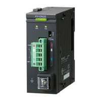
KV-DN20 |
|||
|
Image |
|
|||
|
Type |
DeviceNet® unit |
|||
|
Communication protocol |
Compliant with DeviceNet® |
|||
|
Transmission specification |
Transmission rate |
500 kbps, 250 kbps, 125 kbps |
||
|
Transmission media |
5 dedicated cables (2 for signal system, 2 for power, 1 for shield line) |
|||
|
Connection topology |
Multidrop method |
|||
|
Maximum cable length |
Thick main cable 500 m (Transmission speed 125 kbps), 250 m (Transmission speed 250 kbps), 100 m (Transmission speed 500 kbps) |
|||
|
Maximum number of nodes |
64 (including master, slave, configurator) |
|||
|
Master mode |
Connected pieces per network |
Max. 64 |
||
|
Type of communication |
I/O communication (Poll/Bit-Strobe/COS/Cyclic), Explicit message communication |
|||
|
Type and size of assigned devices |
Relay or data memory (indicated per block) |
|||
|
Assignment method of device |
Auto configuration (Fixed or assigned with front end) and manual assignment |
|||
|
Slave connection pieces per unit |
Max. 63 |
|||
|
Maximum number of I/O per slave |
Input: 2048 points (128 words), Output: 2048 points (128 words) |
|||
|
Data length of message communication |
Sending: 106 bytes, receiving 110 bytes |
|||
|
Slave mode |
Connected pieces per network |
Max. 64 |
||
|
Type of communication |
I/O communication (Poll), Explicit message communication |
|||
|
Type and size of assigned devices |
Relaying or data memory |
|||
|
Internal current consumption |
Internal circuit: 24 VDC 45 mA or less (supplied by CPU unit) |
|||
|
Weight |
Approx. 150 g |
|||
CC-Link unit
|
Model |
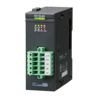
KV-CL20 |
|||
|
Image |
|
|||
|
Type |
CC-Link unit |
|||
|
CC-Link compatible |
If acting as master station: Ver. 2.00, If acting as local station: Ver. 2.00/Ver. 1.10 |
|||
|
Communication standard |
Compliant with CC-Link Ver. 1.10 |
|||
|
Number of exclusive connections |
For local station: 1 to 4 stations |
|||
|
Maximum number of links for 1 system |
Remote input and output (RLY): 9,440, Remote register (DM): Reading 2,048 words/Writing 2,048 words |
|||
|
Transmission specification |
Communication speed |
156 kbps, 625 kbps, 2.5 Mbps, 5 Mbps, 10 Mbps |
||
|
Connection topology |
Multidrop |
|||
|
Connection cable |
Ver. 1.10 supported CC-Link dedicated cable (pair cables of twisted 3-core threads with shield: OP-79426, OP-79427) |
|||
|
Maximum cable length |
Varies according to communication speed |
|||
|
Maximum connectable number of units |
For master station: 64 |
|||
|
Operating station |
Master station, master station (duplex), standby master station, local station |
|||
|
Operating mode |
Online mode, offline mode, line test 1 mode, line test 2 mode |
|||
|
Transmission mode |
Cyclic transmission, transient transmission |
|||
|
Internal current consumption |
170 mA or less (supplied from the CPU unit) |
|||
|
Weight |
Approx. 170 g |
|||
KL-LINK unit
|
Model |
KL-N20V |
|||
|
Image |
|
|||
|
Type |
KL-LINK unit |
|||
|
Transmission specification |
Communication speed |
5 Mbps, 2.5 Mbps, 625 kbps, 156 kbps |
||
|
Maximum cable length |
5 Mbps: 50 m, 2.5 Mbps: 120 m, 625 kbps: 500 m, 156 kbps: 1,200 m |
|||
|
Communication medium |
Dedicated cable (shield line with 2-core threads) |
|||
|
Maximum number of connections for expansion station |
5 Mbps: 97, 2.5 Mbps: 129, 625 kbps: 129, 156 kbps: 129 |
|||
|
Amount of communication data |
Max. 2,048 (128 words) |
|||
|
Communication cycle time |
2.88 ms/2,048 points (Communication speed 5 Mbps) |
|||
|
Internal current consumption |
80 mA or less |
|||
|
Weight |
Approx. 100 g |
|||
High-speed multi-link unit
|
Model |
KV-LM20V |
KV-LM21V*1 |
|||
|
Image |
|
|
|||
|
Type |
High-speed multi-link unit |
||||
|
Connection interface |
Terminal block |
||||
|
Transmission specification |
Electrical termination (Terminator) |
Set by the switch on the front face of main body |
|||
|
Transmission distance |
19,200 bps: 1,000 m or less, 115,200 bps: 1,000 m or less, |
||||
|
Number of transmission units |
15 |
||||
|
Communication speed |
Baud rate: 19,200, 115,200, 0.5 M, 1.0 M, 2.0 Mbps |
||||
|
Connection topology |
Multidrop (Unable to separate) |
||||
|
Connectable CPU units |
KV-8000/7500/7300/5500/5000/3000 |
||||
|
Internal current consumption |
120 mA or less |
||||
|
Weight |
Approx. 110 g |
||||
|
*1 The specifications may differ depending on usage. Check your manual for more information. |
|||||
Error output unit
|
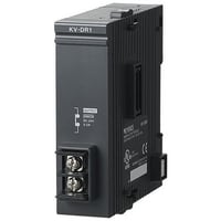
Model |
KV-DR1 |
|||
|
Image |
|
|||
|
Type |
Error output unit |
|||
|
Error output |
Output form |
Relay |
||
|
Rated load |
24 VDC 0.5 A |
|||
|
ON resistance |
50 mΩ or less |
|||
|
Response time |
OFF to ON 10 ms or less, ON to OFF 5 ms or less |
|||
|
Relay life |
Electrical life: 100,000 times or more (20 times/min.) |
|||
|
Relay exchange |
Impossible |
|||
|
Internal current consumption |
5 VDC 30 mA or less (supplied from the CPU unit) |
|||
|
Weight |
Approx. 90 g |
|||