Industrial Laser Marking Systems / Laser Markers
UV Laser Marking
UV laser markers use ultraviolet light, typically at a 355 nm wavelength, to mark or process materials. This wavelength, about a third of the typical fibre, allows the UV laser to do things that no other laser marker can. The shorter wavelength delivers significantly higher absorption and a much smaller beam spot. This allows for high contrast and damage-free marking on metals and plastics, as well as the ability to mark smaller or more precise parts. This makes it an ideal solution for heat-sensitive materials or parts requiring precision that typical fibre lasers cannot achieve.
What is a UV Laser?
To produce a UV laser, the laser beam passes through two additional crystals that conventional fibre laser systems lack. First, By passing a standard wavelength laser (1064 nm) through a nonlinear crystal, the wavelength is reduced to 532 nm. Then, this light is further passed through another crystal, effectively reducing its wavelength to 355 nm. As a result, UV lasers are commonly called third-harmonic generation (THG) lasers because they are the third wavelength created. Marking using these lasers is called "Cold Marking," which refers to how they can perform marking and processing with minimal heat stress.

Why Choose UV Laser Marking?
Manufacturers across the globe use UV laser marking due to its precision and ability to work on sensitive materials. The shorter wavelength (often 355 nm) allows UV lasers to create detailed, high-contrast marks on materials like plastics, ceramics, and glass without causing heat damage. Using a UV laser marking machine allows for minimal material alteration, which is especially important for marking items like microchips or delicate medical devices.
UV laser markers are the best option for marking materials that reflect longer wavelengths when compared to other laser technologies. They excel at creating clear, high-contrast marks on transparent or highly reflective surfaces. In contrast, other lasers, such as infrared or CO2, struggle to achieve the same level of precision without causing damage.
The precision offered by UV laser technology also ensures that barcodes, logos, and detailed product information can be clearly marked, even on the smallest components. One final reason UV lasers are often chosen is that they operate at higher speeds. Production efficiency, while maintaining the quality and durability of the markings, is easier to achieve.
UV Laser Marking vs. UV Laser Engraving
The distinction between UV laser marking and engraving lies in the depth and technique. UV laser marking typically alters the surface layer of a material to create high-contrast marks, but it does not remove material. Ideal for applications where permanent, non-invasive marking is needed, marking is useful where surface integrity must remain intact.
On the other hand, UV laser engraving uses a deeper process, physically removing material from the surface to create more tactile designs. Laser engraving large surfaces or designs can be more difficult with UV lasers, due to the lower heat reliance. However, the high energy density and small beam spot make the UV laser a good choice for precision cutting for thin materials that can't sustain heat damage. While both techniques offer precision, UV laser etching machines are best for products that need to retain their surface properties while still benefiting from long-lasting, high-contrast markings.

UV Laser Marking Applications
As mentioned, UV lasers feature a highly absorptive wavelength of 355 nm. This is dramatically shorter than general laser marking and processing systems, which allows many materials to absorb it at a much higher rate. The shorter wavelength also allows a UV laser to perform "cold marking." This is characterised by photolytic processing of the material bonds to create contrast or remove material.
General lasers use a thermal process of vibrating the bonds of material via heating to the point that they break. This often leads to a heat-affected zone (HAZ), which is a zone surrounding the mark where material properties are changed due to heat exposure. This can damage products or create more scrap.
UV lasers remove the risk of this heat-affected zone as marks stay at a higher surface level while still creating permanency. A UV laser is ideal for almost any plastic, resin, glass, rubber, or ceramic needs, as well as any metal marking or processing application where the effects of laser marking on the materials' surface finish may be a concern.
In-Vehicle Plastic Parts
Polyamide (PA)
Earbuds
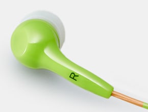
PVC
LED Lights
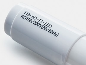
ABS
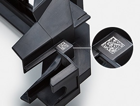
Multicolour Automotive Relays
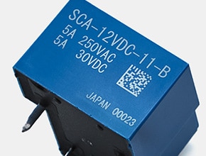
PBT
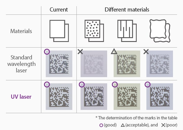
Highly Robust Against Material Inconsistencies
UV lasers eliminate the need for tricky readjustment of laser marking parameters to counteract contrast decreases due to material changes, inconsistent surface conditions of moulded parts, and different resin lots. With high contrast, this robustness provides the characteristics, including resistance against ambient light, that enable marking operation with fewer failures.
UV Laser High-Contrast Marking Application
The FDA requires all but Class I medical devices to contain traceability codes that machines and people can read. The "cold marking" process allows medical manufacturers to mark anything, from PE medication bottles to implantable devices, with the confidence those marks will withstand stringent sterilisations cycles.
Absorption Rate for Plastics
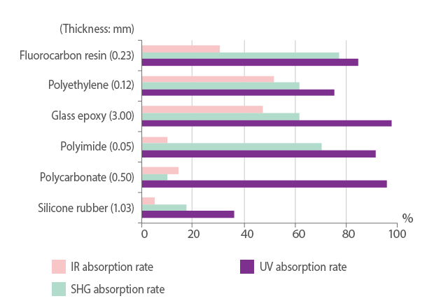
Absorption rates for various resin materials
* The values are for reference only and do not account for surface reflectivity
Absorption Rate for Metals
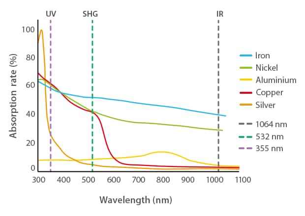
Light absorption rate for metal
UV Laser Marking Feature: Damage-Free Marking & Processing
Why is a UV laser marking machine the superior choice in these types of applications? The main reason it was developed is that the absorption rate is incredibly high for a variety of materials. This allows marking and processing to be performed with minimal heat stress. It also reduces surface damage, allowing for corrosion-resistant marking. These attributes protect the materials or components from issues during the marking and manufacturing process. This is true even for highly reflective materials like gold, silver, and copper and sensitive materials like glass, rubber, ceramic, and plastic.
Perform Both Marking and Processing Without Thermal Damage
Thermal Processing
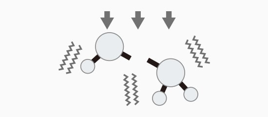
Bonds are destroyed using heat to vibrate the molecules.
Photolytic Degradation Processing
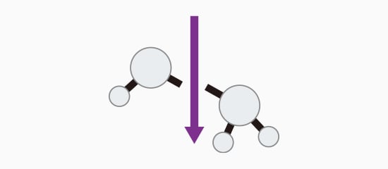
Bonds are broken with light, resulting in less heat.
Conventional
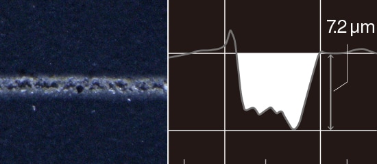
UV Laser
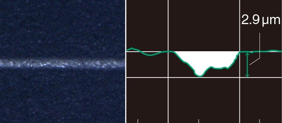
Marking with reduced amount of engraving.
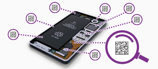
UV Laser Damage-Free Marking Application: Electronic Parts
Electronic parts are becoming smaller, and their sealing resins are becoming thinner. Typical laser markers risk transmitting energy through sealing resins and damaging the internal components. However, UV laser markers have an incredibly high material absorption rate and can mark sealing resins without reaching down to the internal components and risking damage. Since a UV laser marking machine can mark sealing resins, manufacturers can add more identification or traceability marks to electronic part surfaces. Customers and manufacturers get quicker recalls and more up-to-date product information.
UV Laser Damage-Free Marking Application: Quartz Glass
Quartz glass is used for windows or screens and is notable for being difficult to mark. It's sensitive to cracks yet heat resistant, requiring a gentle marking method. The UV laser uses its high absorption and power-dense beam spot to mark slowly and produce clean, visible marks. The UV laser marker beam is strong enough to conquer the heat resistance yet delicate enough not to crack the quartz glass.
Small Beam Spot and High Beam Quality
The wavelength greatly impacts the spot diameter of a laser. Since UV lasers are 1/3 the standard Fibre wavelength, the spot size is narrowed accordingly. This opens the possibility of marking where there is extremely limited space and where marking was not an option before. There is also a continually rising demand for manufacturers to reduce the component size and increase functionality, so the ability of the UV laser to mark the finished product and individual components is very unique.
Issue
An increase in the number of markings required due traceability improvement.
Solution
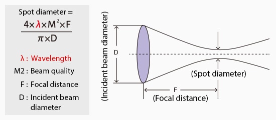
Laser marker spot diameter
Clear marking when space is limited.